No banana for scale, but let’s say that it’s not too big and not too small. The dimensions are 295mm tall, 270mm wide, and 240mm deep. If I had to do it again, I would be tempted to go a bit wider and touch less deep. It’s probably better to be large in one of these dimensions as opposed to both of them.
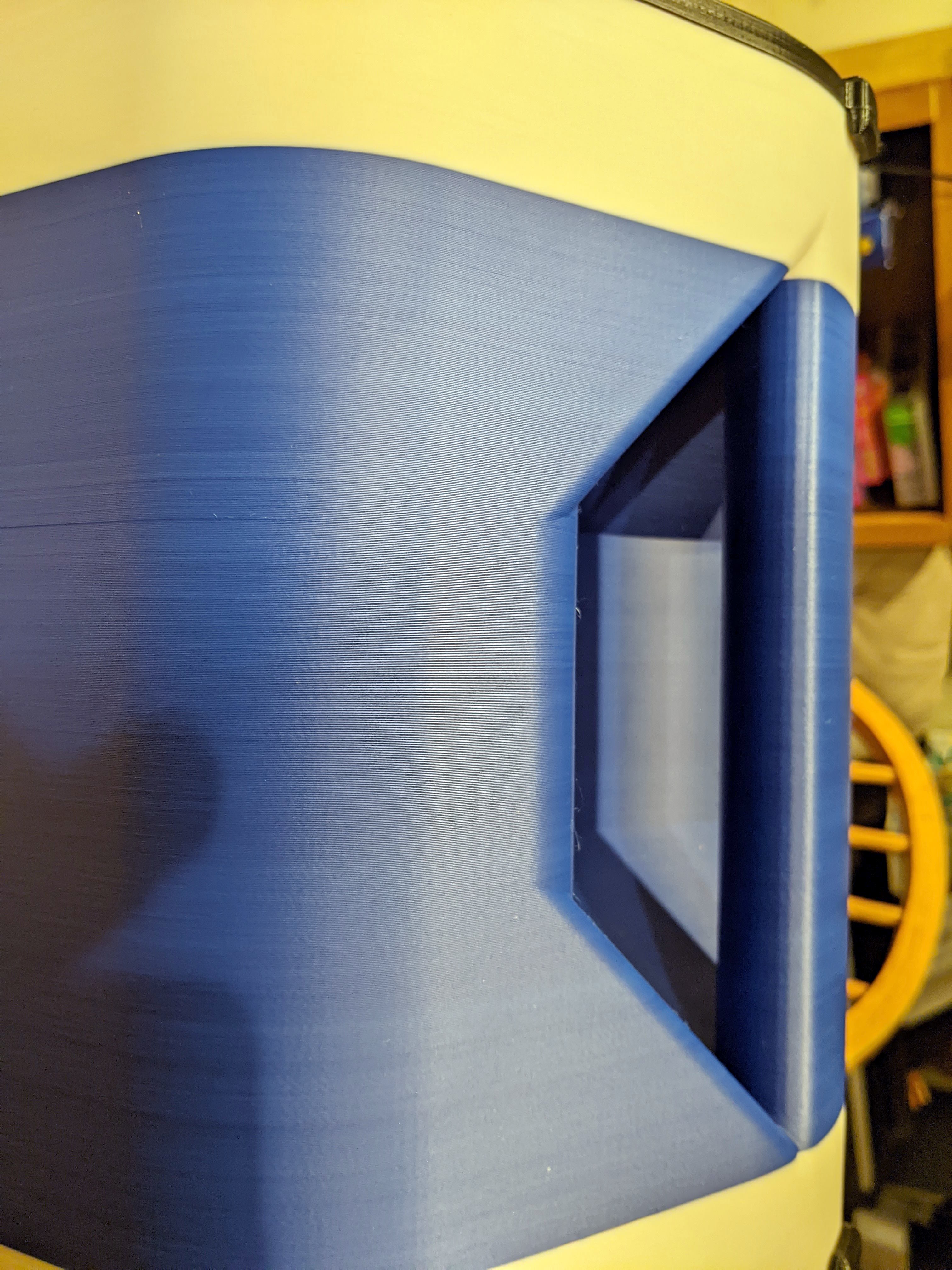
Here’s the top. It has a jack for charging, a connector to program the DSP, a switch to turn it on and off, and a battery gauge.

The speaker also has a built in handle that’s way chunkier than it appears, but is still particle.
The big BOM pieces are a Dayton Audio LBB-5Sv2 for the BMS (battery management system), a Dayton Audio KABD-250 2 x 50W for DPS, amplification, and Bluetooth, a Peerless by Tymphany BC25SC08 tweeter, and an Italian-but-made-in-India woofer (a Coral PRF 165).
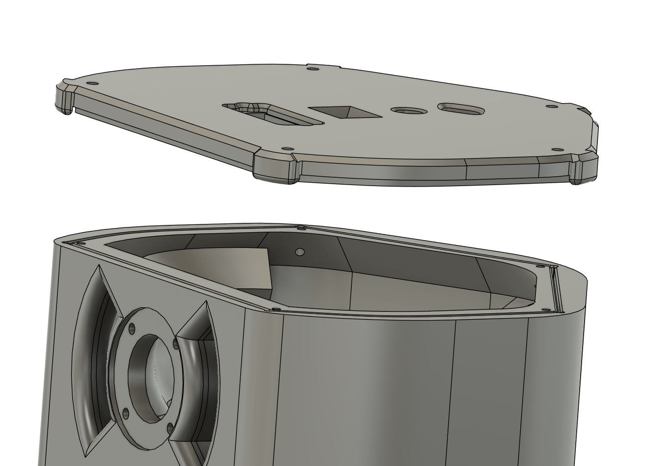
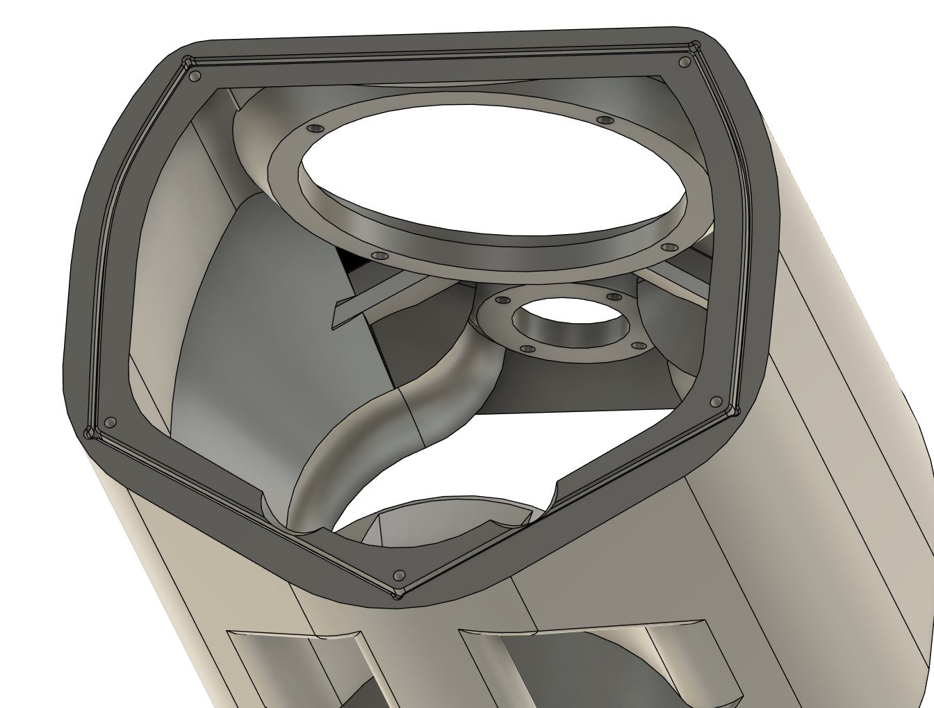
The print itself is three pieces: the bottom bit (black), the middle bit (white, blue, and white again thanks to not having enough white left to do it all in white), and the black top. Here’s a CAD view that more clearly shows the three pieces:

the three pieces are held together with heat-sets and m3 bolts. There’s also a tong and groove like joint to help the enclosure leak less air. I haven’t noticed any evidence of air leaks while listening.
The amplifier and battery board mount to the bottom like so:
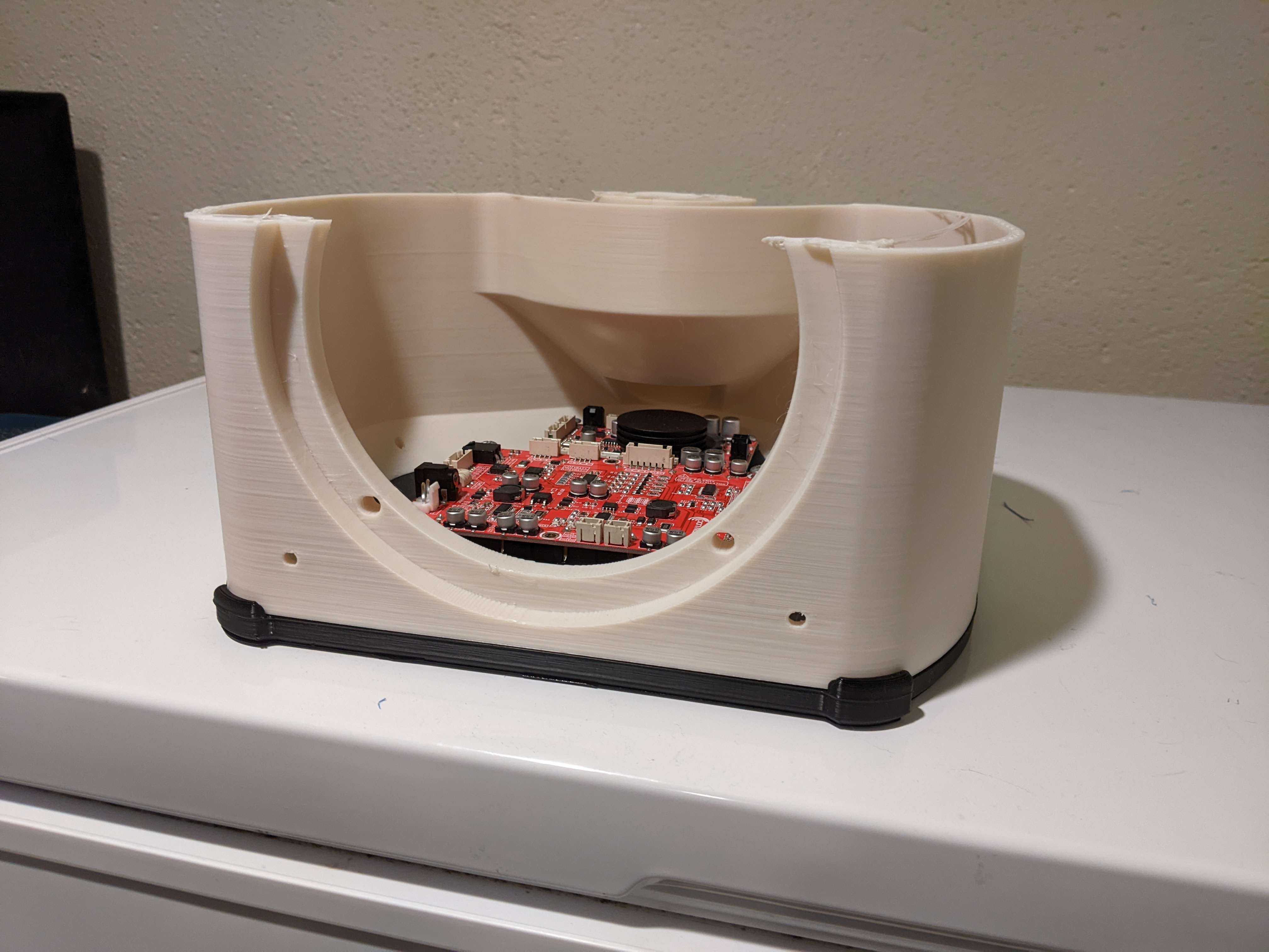
The middle was printed with some supports for the driver overhangs, but the ports and everything else were designed to print in place without supports.

This is certainly not meant to be audiophile build, but it’s surprisingly decent. This isn’t my first blue-tooth speaker, or even my first printed loudspeaker enclosure, but it is the first that was somewhat intentionally designed to have OK bass response while also being reasonably compact.
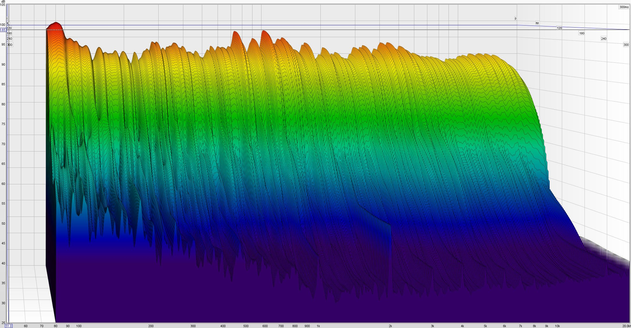
It measures fairly well. Frequency response, along with harmonic distortion, is pretty good. There’s zero windowing or smoothing on this plot. I suspect the distortion spikes at 1 kHz, 2 kHz, etc are induced by the Bluetooth stack the board is running since they’ve shown up in multiple different enclosures and with multiple different drivers.

There’s no nasty ringing, caused by either the drivers or the enclosure, so life is pretty good:
If you do design another one, here’s an interesting technique I saw on a random YouTube video:
Make an enclosure that fits together so that the walls have a cavity between them you can fill with a combination of plaster of Paris and pvc glue.
This, combined with separate chambers for tweeters/woofers/subs/etc and a little thought for how the sound exits the enclosure, and you’ve got a top tier miniature sound system for a fraction of the cost. Although it will be a little bulkier, a little heavier, and takes more time to design, if you want to take another step up from what looks to me like a pretty good first one. Honestly given the 3d printed enclosure I expected all kinds of distortions and noise, but you clearly did quite well. So please don’t for a second think I’m trying to say “uhh this way is better” it’s just a different way, and one that could be better or worse for many many reasons.
I’ve seen that approach taken to make the enclosure more “dead”, but at these power levels it doesn’t really matter a lot. The walls are 1.8mm thick with 30% infill. The top and bottom are PETG and the middle section is ASA. These materials are more ductile than say PLA, so they’re inherently slightly deader.
You’re absolutely correct that the approach you suggested would result in a slightly better outcome for a bit more weight to lug around and a little more design effort. It just didn’t seem worth it to me for this portable and fairly low power application.
Fair enough, given the small dimensions I figured lightweight and easy to repair/replace is the biggest feature you’re going for.
I considered adding in a “for if you want to take a step up” to it, but that sounded to me like I was trying to say yours is somehow lesser, which is definitely not the case.
Too bad videos can’t give a good idea of sound quality, because I’d love to hear it. Based on the specs I can see, this thing should be a nice little powerhouse in it’s own right!
It would totally be a step up, the question is which step ups are worth it given the BOM components and their cost (around $200 for all the electronics and drivers excluding plastic). At the end of the day it’s a $20 tweeter and a $45 (used) car door woofer connected to a fairly cheap class D amp using Bluetooth. It has a slight turn off pop (no turn on pop though), it hisses some at idle, you can hear the noise floor decrease (eg more noise) when a Bluetooth device pairs, Bluetooth itself isn’t a super awesome media for audio (it is a lot better than it used to be, but your actual quality will depend a lot on device to device configurations), etc etc.
I’m not sure what I would prioritize first for the next step up in SQ, but I don’t think it would be the enclosure itself.
This is awesome. I’ve been wanting to make a speaker. I think there are a lot of possibilities in a 3d printed enclosure that do not exist with conventional building methods. Something I’d like to try is blending wood and a 3d print, perhaps wood top and bottom with a 3d printed center.
Thanks for sharing.
Go for it! 3D printing unlocks the opportunity to easily fabricate things that would be pretty difficult to make out of only wood. I’m mulling over making a baby array of BMR drivers https://www.tectonicaudiolabs.com/audio-components/bmr-speakers/
Did you do anything to increase the density of the cabinet for better acoustics? I know other 3D printed designs have you fill the empty space with concrete. Also if you ever design more speakers you should try out a paraflex design, it’s an open source style of speaker that emits a cardioid dispersion pattern on the low frequencies which makes it possible to aim those frequencies without involving a DSP and math. Unfortunately their main group is on Facebook though https://www.facebook.com/groups/bassaz/
Another commenter in here suggested filling the gap with concrete. I don’t think it’s worth it at this power level, cheapish BOM, etc. The enclosure is also ASA (the middle) and PETG (the top and bottom), so it’s a bit more dead than PLA already.
That looks like an interesting design. If you’re linking to something like that, you’ve heard of Hoffman’s Iron Law already. I chose size and low end response over efficiency. I did model some higher order enclosures, but they either didn’t get low enough (size, efficiency) or were too big (efficiency, low end response).
Really impressive. Thanks for sharing!
ok this one is pretty cool.
just wanted to say good work. carry on.
It looks awesome! I’ve always wanted to mess around with printing a speaker enclosure. Did you put any specific thought into the enclosure regarding acoustic tweaking?
I wonder how the frequency spectrum looks compared to the speakers without any enclosure.
Thanks! There are two “big” details that I did think about to some extent.
The first big choice was what kind of enclosure type I wanted. This winds up running into Hoffman’s Iron Law, which means choosing two: low end bass, efficiency, and size. I chose size and low end bass, which means that I went with a traditional ported enclosure. I did consider, and spent some time modeling, a more exotic double bass reflex enclosure, but it just wound up being too large. Modeling in this sense involves acoustic modeling, which I did in WinISD for the ported enclosure and Hornresp for the double bass reflex, and physical modeling, which I did in Fusion360. I also selected drivers that would play fairly well with one another.
The second was geared more toward printing. Curved surfaces resist flexing more than flat surfaces, so most everything is curved or has a reinforced (eg the top and bottom). I wanted to minimize the need for supports, so the ports have “built in” supports. There’s also the tongue and groove thing for the top and bottom to minimize air leakage.
As far as the drivers without the enclosure, an enclosure adds two things:
- Low end extension. Woofers in free space have extremely limited bass response. In this sense an enclosure is good
- Diffraction and baffle step. This is part of the reason why the sides of the front baffle have a massive radius on them. In this sense an enclosure is bad
I just splooshed. Never have I seen a sexier lemmy comment than that.
Ha, thanks!
Nice project, I love that you analyzed the audio as well! But really? A barrel jack for charging? Make it USB-C!
Or both, as the barrel jack is much more robust than the USB-C connector.
Laziness and easy BMS board compatibly, but I totally understand the sentiment. It’s not like I can’t print a new top if/when I discover an easy/drop in solution that deals with negotiating power and voltage.
Looks great!
What an awesome project - thanks for sharing the details!!
Thanks!
Funny timing. I just saw that a YouTuber I’m subscribed to has a scheduled live stream about 3D printed speakers.
Here is an alternative Piped link(s):
https://www.piped.video/live/Ujeg9fU2UVw
Piped is a privacy-respecting open-source alternative frontend to YouTube.
I’m open-source; check me out at GitHub.
Awesome project. Reminds me of Hexibase YT type stuff. I’ve got a spares shelf of drivers but would need to build an Arduino project to characterize them and the output empirically, and still haven’t gotten motivated for that level of math project.
I assume PLA? If that is ABS I’ll lose my mind.
Thanks! Hexibase’s builds are super cool.
If by characterize them you mean measure the driver’s t/s parameters you can do it with a multimeter, a resistor, and basically any amplifier using a computer to generate the frequency. Elliot can be a bit verbose, which makes his instructions somewhat hard to follow at times, but here’s a guide: https://sound-au.com/tsp.htm
The top and bottom are PETG. The middle section is ASA. 0.6mm nozzle, 0.3mm layer height, 150% extrusion width, two perimeters and 30% infill. I was cruising, but did limit my max flow rate to 25 mm^3. I could have gone even faster, but I was in the rate of diminishing returns for print time. I printed it in my Voron, but it did need some extra insulation to get the chamber temp high enough to avoid warping. The print completing completely successfully told me it’s possible to do big ASA prints with a 60 degree chamber temp, so I’ll be spending the time to make some nice insulated ACM panels.
That is freaking awesome! I tried both ABS and ASA with the MK3 and a sealed enclosure, I can do some fairly large prints up to something like large grapefruit scale, but anything like your enclosure will separate on the corners. I think it is simply a bed slinger issue that is unsolvable. Awesome to see the tangible results and justification for building a 2.4.
I had prints doing exactly what you described on my CoreXY because ABS and ASA are very warp prone. For me it all came down to chamber temperature and a solid first layer. I think you should be good to go on the latter thanks to your MK3.
You’ll need active chamber heating at a minimum to pull off larger prints. This doesn’t necessarily mean an aux heater, but it does mean bedfans. I’m not sure how easy those are to implement on a MK3, but I would be amazed if no one hasn’t figured out something, especially given the size of the community. In my case, I’m using 4x bed fans with two doing double duty in a filter.
My printer is a 350mm^3 Voron, which means its acrylic panels are fairly large. More surface area means more heat loss, so I need panels that do a better job of retaining heat than simple acrylic. This might also be the case for you thanks to having to move your bed back and forth. I’m hoping that ACM+radiant insulation will get me there. This print happened in a 60 °C chamber.
Here is an alternative Piped link(s):
Piped is a privacy-respecting open-source alternative frontend to YouTube.
I’m open-source; check me out at GitHub.


