
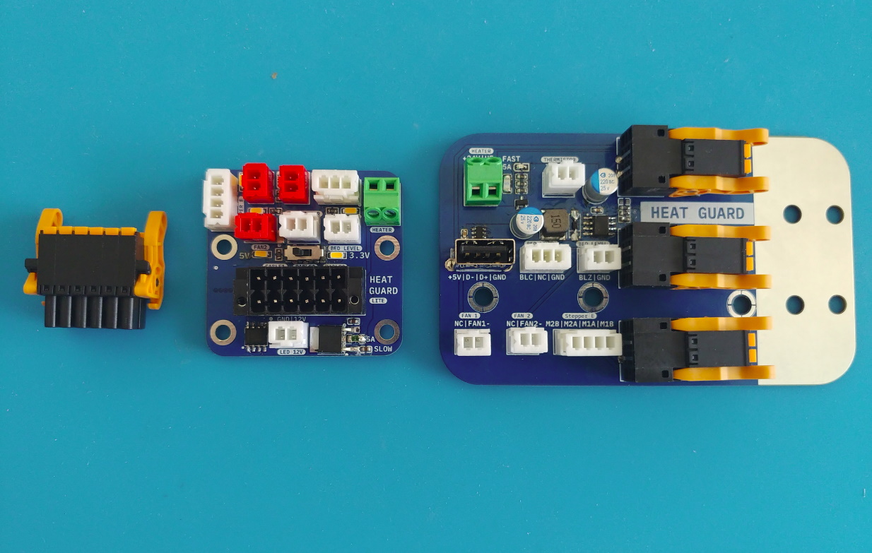
Three years ago I looked into properly wiring hotends with quick toolhead swapes and came up with this: Combining the entire hotend wiring into 3x shielded 4-conductor cables (thin cables for small drag chains with tiny bending radius) and options to terminate the shield. The static side features an USB-port to retrofit Raspberry Pis and a step down to generate the 5V supply from a single 12 or 24V power input.
For the moving side/hot-end PCB it’s a similar story:
- stepdown to 12V for fans and LED lights
- stepdown to 3.3V and 5V
- selectable logic voltage (3.3V, 5V)
- temperature and humidity sensor (feedback for heated chambers: adding a measurement point close to the print or being able to measure any point within the chamber to check for uniformity during development)
Why did it all fall apart? BOM cost.
Those connectors with locking lever for easy removal cost a fortune and the 3D-printing world moved on to CAN.
For the active version of this, it’s a different story. Never figured out how to make it plug-and-play/foolproof (active circuit for safety features (contact resistance, overtemperature, fan failure, etc.) as well as preemptive maintenance (heater wear, fan bearing degradation, and more).
I just put a toolhead board on one of my ender 3s a couple weeks ago, it was a pain in the ass and not necessary in any way but I’ve since pulled the toolhead off twice and both times it was nice just detaching the single connection and being able to move to my desk to do the work.