

I thought I would knock some dust off my drafting skills after a small chat with @captain_aggravated@sh.itjust.works
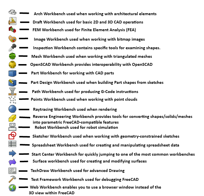
Seeing this image on the tutorial made me realize, FreeCAD seems to be a Technical Geometry Super-Suite. It makes sense that CAD would grow to include all of these things. But I thought sharing the initial perspective of some one who hasn’t looked at this stuff in about 18 years might be interesting.
Granted I’m not actually familiar with most of this stuff, and none of it from the POV of FreeCAD. If this can deliver 10% of what I’m looking at, I’m in for a treat.
Seems like a good opportunity to ask if anyone can recommend learning materials for FreeCAD? Used Solidworks and AutoCAD in school but fell back on tinkercad for a recent project just cause I didn’t have time to invest in learning.
This is a pretty good tutorial to get started in FreeCAD. Just watch out for the topological naming issue. They still haven’t fixed it, but if you know how to avoid it, you shouldn’t have too much trouble.
Parametric is such a leap, when coming from toy blocks like TinkerCad in which I can really easily do all that I want except those sexy fillets…
I really want to learn it but it feels so convoluted and difficult. I’m aware that FreeCAD is not the easiest, and some commercial packages are easier to grok but their licensing is really hostile to simple hobbyists so I am trying to to take the high road, for now anyway.
Hey, I have used freecad a lot. FreeCAD is good, not great as a cad software. But it is the only truly “no strings attached.” The problem with it was development was almost at a standstill for things that actually mattered. A new company has formed around commercializing it and are working with the original Dev team.
Updated UI, topological naming fix, some assembly and actual functional defaults were promised for Q1 2024 and releasing it as a 1.0 version.
I think it is worth it to learn how to use right now as in the next 2 years it should become an actual viable CAD alternative for things outside of simple projects.
I wouldn’t try parametric models in freecad. They use a really really bad spreadsheet reference system that recalculates you model, not on every change, but every CLICK which means that when you have a variable that is reference more than 10 times or so, it begins to take longer and longer to even start to enter a new value. One time it took 5+ minutes just to get into the spreadsheet cell before even being able to edit its contents.
For parametric, use OpenSCAD (or openscad in freecad) until they implement actual, working variables.
I would clarify that you’re talking about a specific usage case, that OpenSCAD does indeed do better at. However for most CAD tasks I find OpenSCAD is overkill and less intuitive.
“Parametric design” usually refers to the workflow used in the Part Design workbench, as well as SolidWorks etc. where geometry is defined by constraints.
The Part Design workbench does work well and despite the topological naming issue is sufficient for most hobbyist and many light industrial tasks. If I need to draw up an arbitrary bracket or bushing or similar, I don’t even bother using a workflow that guards against the issue, I just use it casually like I would SolidWorks. Only if the part is complex or if I know it will need to be tweaked do I bother doing everything on datum planes etc. because it’s a lot slower and more hassle.
That’s very good news that the topological naming issue is being solved, though. #1 issue with FreeCAD IMO and the one that holds it back from serious industry use.
That’s how parametric workflows work in some industries. In the architecture world of Rhino / Grasshopper and Revit / Dynamo, the expectation is that parametric scripts can do almost anything.
If you don’t want to make parametric models, you can build simpler things by combining primitive shapes in the FreeCAD part workbench. You can even fillet and chamfer them.
The dirty secret of FreeCAD is that most drawings that look okay will extrude even if unconstrained. You just lose the ability to leverage the history tree and the model will be as brittle as any direct modeler’s.
FreeCAD is on its way, it’s attracting a little more money and attention, and I’m using it more and more, but I often still feel like I’m fighting it.
Mind. Blown. I had honestly not thought of that possibility. And you say fillets work? Wow, have to try that. Thanks!
I have found one issue with FreeCAD fillets: it doesn’t like it if they touch, that is…draw a rectangle with thickness of 10mm, and then apply a fillet around the top and bottom surfaces of 5mm radius, which would produce a perfect 10mm diameter. It doesn’t like doing that. 4.99 will work, but not 5.00. If you want a perfect half circle on the edge of something like that, you have to draw that another way.
That is an insane bug to have in your CAD software, I don’t see how it’s usable for any slightly complex part.
Literally every CAD program suffers this to a greater or lesser degree. There are workarounds but they’re clunky.
The issue with FreeCAD is that all the workarounds (so far) are manual. Other apps may well be doing similar things, but they’re doing them behind the scenes and the user doesn’t have to (for instance) specifically set up a datum plane offset at the exact same distance as the face you want to sketch on and either manage it by hand or use an integrated spreadsheet to set up and reference variables.
I like what I see coming out of FreeCAD these days, but stuff like that is… umm, a lot.
Here is an alternative Piped link(s):
This is a pretty good tutorial to get started in FreeCAD
Piped is a privacy-respecting open-source alternative frontend to YouTube.
I’m open-source; check me out at GitHub.
deleted by creator
I find that Onshape is quite good and is all browser based so it runs quite well on linux.