Hi c/FreeCAD, totally newbie here! I’m having a ton of fun learning FreeCAD, but I have a small question. I know the toponaming problem is going away soon, and maybe that makes this kind of irrelevant, but I’d still like to know.
Sometimes when I’m watching or reading guides on avoiding the toponaming problem, the person will say something along the lines of: “actually this technique is also more professional/proper/correct anyway, real engineers do it this way.” Basically that the methods that avoid the problem are also just best practices in general. But they always say that as kind of an aside, and I wish they’d say more! What makes those methods better? Does anyone have any suggestions for articles or videos about this?
For one example, there was one guide that suggested you should use a datum plane instead of referencing one of the object’s surfaces. I understand the toponaming problem well enough to get why referencing a surface can cause it. However, the person in the guide used the same surface that would have been referenced, as the attachment point for the datum plane. Why does that not produce the same issue?
The best I have is to be careful to minimize dependencies, and minimize when I change the number of faces an object has, but of course that’s unavoidable sometimes. I don’t buy it that all CAD tools have the same problem or that this is how real professional CAD designers would work, though.
To minimize dependencies for example, instead of drawing the sketch for pad 2 directly on a face of pad 1, I might draw it on the base plane and transform the sketch to line up with pad 1’s face. The main consequence is that I need to manually move pad 2’s sketch if I change the size/position of pad 1. It’s a tradeoff, because I’m giving up some of the benefits of parametric CAD in exchange for easier fix-up.
I agree, mapping a datum plane to a face should have the same topo naming issue as just drawing on the face, so I don’t know why the guide would suggest that. The comment below about mapping datum planes to a simplified skeleton is interesting though.
The good news is that the next release (which sounds imminent) apparently improves it quite a bit.
When I’m using FreeCAD, I’ll use a spreadsheet for all of my variables, so everything is linked together by formulas. Next, I’ll use datum planes rather than drawing directly on object faces (which completely solves topological naming), although I wouldn’t attach the plane to the surface–just geometrically define the distance and angle in the spreadsheet and reference it directly (e.g. if I want a datum plane halfway up my object, I’ll make its height h/2)
It is good to note that the datum plane technique completely breaks sometimes when changes on earlier shapes when dealing with angles and rotation, and non-planar geometry unless you reference it to a face (in which case topo naming again) because rotation of a datum plane is rotated and shifted with respect to the origin and not the desired face. Not to mention getting an exact face takes a long time of tweaking with complex parts.
Also be careful with spreadsheets. Is one variable is referenced more than 15 times or so, every mouse click in the spread sheet starts taking minutes to calculate. I had an outer shell dimension in a PC case in a design that I referenced a lot and clicking a spreadsheet cell would trigger an 8 minute recompute before I was even able to enter the cell to edit the variable (so then another 8 minutes after editing)
I’ll use datum planes rather than drawing directly on object faces
I haven’t had a chance to try FreeCAD, but this is generally good advice in other parametric CAD tools, too. Create “skeleton” features early on (planes, datums, simple sketches) and define later features by referencing the skeleton as much as possible. It avoids creating a long chain of feature dependencies where Feature A changes and breaks Feature B, which breaks Feature C, etc.
Ohhh, that’s brilliant! I’ve been using named sketch constraints and then formulas referencing those so far, but AFAICT you can’t seem to name the parameters in pads/pockets/etc? Using a spreadsheet sounds much better, thanks!
What makes those methods better?
Disclaimer, I’m at a sortof “advanced hobbyist” level of cad. My understanding of the topological naming problem in general is that it exists in all cad because it is a sortof byproduct of how computers keep track of data about 3 dimensional objects. If you make a cube, all the sides need to have an identifier associated with them. If you put a hole in that cube, you now have more identifiers and have to decide what ordering makes sense. It sounds easy to work around with a cube but when models get really complex it’s not so easy, especially when you change something way back at the beginning which creates more or less faces in the middle of the list somewhere.
Freecad isn’t making the topological naming problem “go away”. They are creating (or rather merging, it’s been around a long time) an algorithm that makes a better guess at what the order should be, rather than sticking new faces in the list and reordering without any consideration of what happened after that face was created. This is, as far as I understand, also how other CAD packages do it, and you can still back yourself into a topological naming problem if you try hard enough (or don’t try at all I guess) in both freecad with the new changes applied, and in other CAD packages.
So “best practice” is to be smart about the attachment of your geometry thinking about how things might change in the future, rather than clicking the closest face whenever you need a sketch plane. In reality modern proprietary cad is so good at guessing and maintaining consistency that it doesn’t matter unless your model is horrendously complex and whoever made it didn’t pay any attention to laying out the base sketches in an organized way.
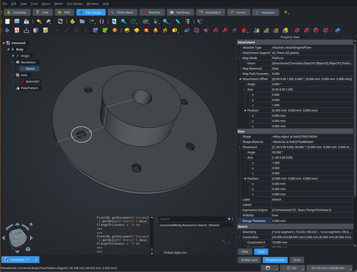
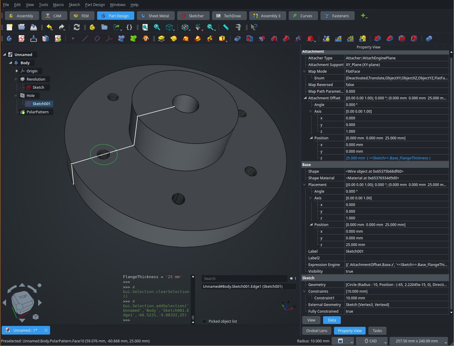
For example if you make a flange but you’re not quite sure about the thickness, base the sketch for say, the holes, on the parallel origin and offset it by the height of the pad or the length of the sketched geometry. Or use a spreadsheet or variableset for the value of both the thing that you define the thickness with, and the offset from the origin plane. That way if the value changes, nothing will break.
I made a test model but it isn’t something that shows up well in a single screenshot unfortunately. See the “Flange Thickness” and z offset parameters in the property view. I used that for the flange dimensions, and the hole sketch offset.